Arduino : Monitor Solar Panels Production (Part 4)
We did a lot of very interesting work so far and we already have a nice working product. However, I have the feeling it is lacking in few aspects. Especially the visibility of its own status and something showing it is working and reporting the data correctly.
I want a Screen !
Indeed, if we have a screen on the top lid displaying the latest measure and some useful information it would be awesome !
Ok, but there are a lot of displays available on the market all with advantages and inconvenience. TFT, LCD, OLED, 7 segments, e-paper, ... ? Ok ok .... What could be the parameters to consider ?
The price of course, probably one of the most important, but money aside : power consumption, size, colours, refresh rate, resolution, ...
Here are few of the displays I currently have in stock ...

- LCD display 2 lines
- TFT display 240 x 240
- OLED display 128x64
- OLED display 128x32
They all serving different purposes, have pros and cons, let's try dig a little bit more.
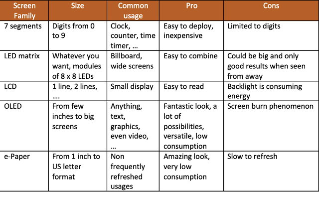
On top of these characteristics, you also need to consider the way these screen can be interfaced in your code and how many PINs they are using. There are 2 big families : I2C and SPI.
I2C is usually using 4 PINs and SPI 6 or 7. It has an impact on the size of the code in your Arduino. Some displays required more memory to be able to run - because of the library size.
With this, I decided to go with the OLED version for his price, power consumption and versatility.
Display ? What for ?
As mentioned above, right now the project is not reporting anything more than 2 status LEDs. Blue is on when connected to the WiFi and yellow is blinking when sending data. Ok cool, but if I need to see the current power ?
In the current situation, there are 3 options :
- Connect on ThingSpeak;
- Connect on Domoticz;
- Plug the box on a laptop with a USB cable
But what if I quickly want to check if the power is still reported accurately by comparing my inverter display and the current measured by the IoT device ? Today, there is no option. This is the reason why I would like to have the latest measure displayed on a screen. Cherry on the cake, a countdown letting us know when the next measure will be taken.
Screen Layout
At this point we have to decide how to display this information. The screen I've chosen is a 128x64 matrix of dots. They can be turned on independently, so we have to control everything.
My final layout idea is to divide the screen in two sections : top section the power, bottom section the countdown to the next measure. All nicely presented in a clear way with rectangle to separate the different sections.
Something like this :

These are of course, dummy data I'm using to simulate the final result. The 2 missing vertical bars on the left and right of the rectangle actually does not exist. There are missing pixels on the picture because the screen is flickering. The screen actually refreshes itself fast enough, so your eyes cannot notice, but my camera can ...
In order to use the OLED screen with the WeMos, we need to use the relevant library with the corresponding drivers. And this is part of the fun :. indeed, finding the right one is not easy.
I'm using the following Adafruit library for this purpose :

#include <Adafruit_GFX.h>
#include <Adafruit_SSD1306.h>
Next, you need to initialize some constants :
#define SCREEN_WIDTH 128 // OLED display width, in pixels
#define SCREEN_HEIGHT 64 // OLED display height, in pixels
#define OLED_RESET -1 // Reset pin # (or -1 if sharing Arduino reset pin)
#define SCREEN_ADDRESS 0x3C
Adafruit_SSD1306 display(SCREEN_WIDTH, SCREEN_HEIGHT, &Wire, OLED_RESET);
Let's create some functions
In order to be modular in my code, I have created 4 functions :
- Turn screen off;
- Show top section;
- Show bottom section;
- Show rectangle
Turning the screen off is trivial, simply use the provided function from the library. Each time you would like to have the changes applied, use the display.display() function.
void turnScreenOff()
{
display.clearDisplay();
display.display();
}
To display the top section, I wrote this function :
void showTopSection(double power)
{
// Remove previous text
display.setCursor(5,15);
display.setTextColor(SSD1306_WHITE,SSD1306_BLACK);
display.print(" ");
display.display();
display.setTextSize(1);
//display.setTextColor(SSD1306_BLACK, SSD1306_WHITE);
display.setCursor(5,2);
display.println(F("Power "));
display.setTextSize(2);
display.setCursor(5,15);
display.setTextColor(SSD1306_WHITE);
display.print(power);
display.print(F(" W"));
display.display();
}
Passing the "power" variable will display its content at the right place. We are positioning a virtual cursor for each "drawing". With our screen size (128x64), top left is 0,0 and bottom right is 127x63.
For the bottom section, I wrote this :
void showBottomSection(int sec)
{
// Remove previous text
display.setCursor(5,46);
display.setTextColor(SSD1306_WHITE,SSD1306_BLACK);
display.print(" ");
display.display();
display.setTextSize(1);
display.setCursor(5,34);
display.println(F("Next measure in"));
display.setTextSize(2);
display.setCursor(5,46);
display.setTextColor(SSD1306_WHITE);
display.print(sec);
display.print(F(" sec"));
display.display();
}
Nothing complex. Next part is drawing the outside rectangle :
// --------------------------
// Display square around data
// --------------------------
void showRectangle()
{
// Draw square around the screen
display.drawLine(0, 0, 127, 0, WHITE);
display.drawLine(127, 0, 127, 63, WHITE);
display.drawLine(0, 63, 127, 63, WHITE);
display.drawLine(0, 31, 127, 31, WHITE);
display.drawLine(0, 0, 0, 63, WHITE);
display.display();
}
Using the function display.drawLine makes the process easier.
I forgot to mention the pinout of the screen. Indeed, to be able to send data to the screen, we have to wire 4 PINs. Positive voltage, ground, clock and data. On my screen labeled as GND, VCC, SCL and SDA.
Nowhere in the code, you will see an explicit reference to any of these pins, simply because there is a standard. GND is ground, so this is easy, VCC is the positive 5V. For SCL and SDA, we are respectively using D1 and D2. This is documented in the WeMos reference guide. It is clearly stated that D1 and D2 are used for SCL and SDA. Always double check with your board manufacturer, but this seems to be a general usage.
How to address the screen burn issue ?
Yes, many screens out there are having the burning issue. It means there is a permanent visible image displayed on top of the new one. This is annoying and the only way to fix it, its to replace the screen.
But we can prevent it ! Indeed, if the screen is powered off after a certain period of time, the phenomenon does not exist anymore !
Is it that easy ? Yes ! we need to maintain a counter which shut off the screen after a certain amount of time. I'm quite confident anything below 5 minutes is perfect. For our usage, I will use 2 minutes. But wait... screen is off, but how to put it back on ? I mean without restarting the unit. Let's add a button, so the button can reset the counter and we have 2 additional minutes. Ok, I think we have our final idea.

I'm using a simple push button and plug it on ground and D6. Let's define some more variables :
// Counter for screen shutoff
int screenTimer;
// Define number of sec screen must stay on - 2 mins is a good practice (120 secs)
int screenOn = 120;
// Push button PIN definition
int button_pin = 12; // D6 = 12
In the main loop, I need to maintain a separate index to control for how long the screen is on and when we hit the screenOn time, it has to be shut off.
[...]
if((screenTimer < screenOn) and (i % 2 == 0))
{
showBottomSection(j);
}
if(i % 2 == 0)
{
screenTimer++;
j--;
}
if(screenTimer == screenOn)
{
turnScreenOff();
Serial.println("** Screen burn protection -> turning screen off");
}
// Wait 1/2 sec between each iteration
delay(500);
[...]
Note : do not pay attention to the i%2==0 test, this is a trick since I'm measuring every 1/2 sec ... so I need to to the check 1 time out of 2 ;)
If the button is pressed, I reinitialize the counter to its minimum value : 0
[...]
if(digitalRead(button_pin) == LOW)
{
Serial.print("** Button PRESSED -> ");
Serial.print("Wakeup screen for another ");
Serial.print(screenOn);
Serial.println(" seconds.");
screenTimer=0;
// Display other section of the screen once
showRectangle();
showTopSection(Average);
showBottomSection(j);
}
[...]
All this is merged with the original code, and it works flawlessly. You can find PhotoMeter v2 on my GitHub here.
So, is this actually working ?!?
.gif)
It is indeed working perfectly. One remark : you need to press long enough to have the push detected within the 500 ms loop. It could be improved by creating an interruption, but I'm not there yet.
So with all these additions, how is this impacting the global schema ?

Changes are : I've added 2 JST-style connectors. One on the left for the OLED screen and one for the button. The JST connectors are very easy to use. Remember, we have the option to remove the lid, and with the screen and button and the 2 LEDs attached to it, it will be easier with detachable connectors.
You can get JST connectors in an assortment box similar to this one. I also bought pre-mounted JST cables (4 pins as well) to simplify the whole process.
What about the Enclosure ?
Do you remember the 3D design ? Now, we need to integrate 2 new items : the display and the button. With 3D design, almost everything is possible :

When designing an enclosure, the challenge is to make sure everything is fitting inside the box. I took this opportunity to increase the height of the bottom section. Indeed, the screen is taking extra space with the PINs, same issue with the button.
You can get the STLs here.
At this stage, we are ready to build the new version ! Little modifications are required on the PCB to accept the button and the screen, but this is minor.
To be honest, the most complicated part of this project is to perfectly align the display with the hole we have created in the top cover. I struggled until I decided to use some rubber band to maintain the screen at the right place and YES !


When the screen is secured at the right place, I glued it with some hot glue - always working great. Make sure to write down the negative PIN to avoid connecting it wrongly.

I've created a custom made connector using female DUPONT connector and a some Heat-shrinkable sleeve. It looks quite nice to me !

Upgrade time !
Let's repack everything in our enclosure. Should not have any problem reconnecting everything if you follow the schematic above.


BOM (Bill of Material)
To complete this upgrade, you need a screen and a button. I also used a new 3D printer filament : PLA+
- The button;
- The Screen;
I've noticed the PLA+ is indeed stronger then regular PLA. I'll remember this for my next projects.
What's next ?
It's becoming more and more cool, but it can be even cooler !
- Creating my own PCB;
- Debug WiFi drop;
- Create a real product image
In case of you missed the previous episodes :


Comments
Post a Comment
Thank you for your message, it has been sent to the moderator for review...